


The MS72SF1 is a millimeter-wave radar sensor module designed for people detection and smart control applications. This guide provides an overview of the hardware, setup process, configuration commands, data protocol, firmware upgrade procedure, and troubleshooting tips to help developers quickly integrate and deploy the MS72SF1 module.
The radar module integrates RF components for sensing.
1. Power Consumption:
lRF enabled: ~530 mA
lRF disabled: ~80 mA
lAverage current (100 ms frame period): ~110 mA
2. Power Input: Requires a stable 3.3 V supply with at least 1 A current capability.
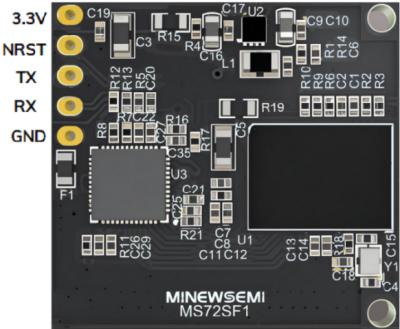
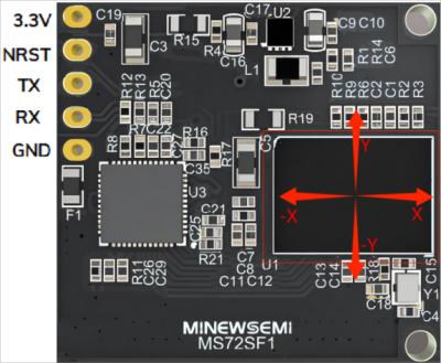
3. Pins:
l3.3V – Power supply
lGND – Ground
lRX/TX – UART communication
lNRST – Reset pin (active low, normally floating)
Step 1: Connect the module to a PC via a UART-to-USB adapter. The wiring is shown in the table below.
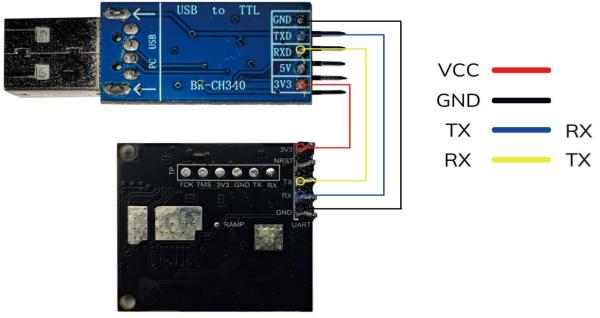
MS72SF1 Pin | UART to USB Pin | |
3.3V | → | 3.3V |
GND | → | GND |
RX | → | TX |
TX | → | RX |
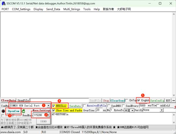
Configure the serial communication tool by selecting the corresponding port detected by the computer, and set up the link as follows:
lBaud rate: 115200
lData bits: 8 bits
lStop bits: 1 stop bit
lParity: None
lCH340 chip driver download: CH341SER.EXE
Note: During the learning process, ensure that there are no people within the radar's detection range. Frequent movement of personnel may cause the learning results to become invalid!
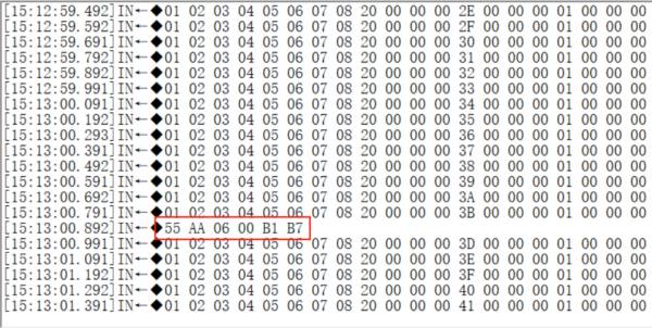
First, send AT+RESTORE\n to restore the module to its default settings, then send AT+STUDY\n. The information returned is as follows: | |
55 AA 06 00 B1 B7 | Indicates that the detected scene differs from the interference positions stored in flash. |
55 AA 06 00 A1 A7 | Indicates that the detected scene matches the interference positions stored in flash, and the new positions will be recorded to flash. |
Data format:
The first two bytes 55 AA are the header
The third byte indicates the data length
The fourth byte indicates the data type
The fifth byte indicates the data result
The sixth byte is the XOR checksum
Step 4: After powering on, send AT+RESTORE\n to restore the module's configuration, then send AT+STUDY\n to enter learning mode.
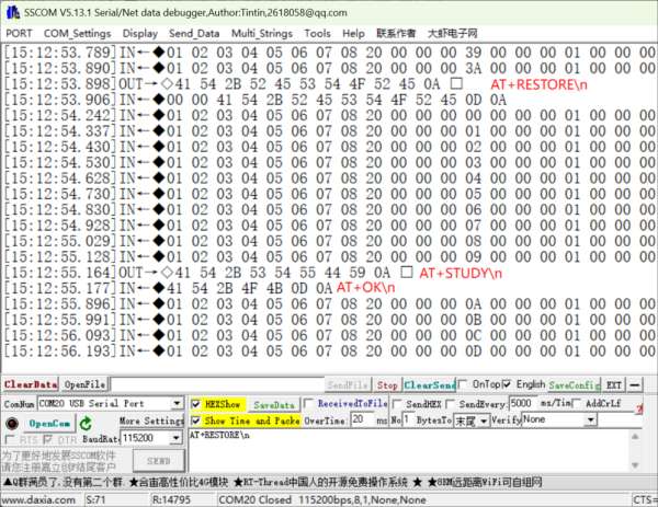
The results will be output approximately 10 seconds after AT+STUDY is sent successfully.
1. When the module outputs 55 AA 06 00 B1 B7, it indicates that the detected scene differs from the interference positions stored in flash. Learning has successfully started. After 10 minutes, AT+RESTORE\n can be sent again to save the data to flash and formally start usage.
2. When the module outputs 55 AA 06 00 A1 A7, it indicates that the detected scene matches the interference positions stored in flash. The new positions have already been recorded to flash, and no further learning is required.
Step 5: After the module outputs 55 AA 06 00 B1 B7, wait for 10 minutes, then resend AT+RESTORE\n to restore the module. At this point, the environmental information has been saved to flash.
Configuration Parameters
Command | Description |
AT+RESTORE\n | Restore Default Settings |
AT+STUDY\n | Start STUDY Mode |
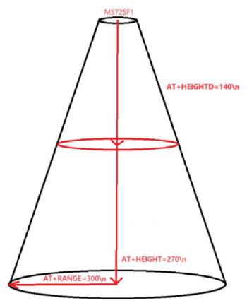
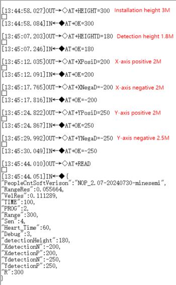
AT+HEIGHT=270\n | Configure the radar installation height (unit: cm, range: 250–320, default: 270) |
AT+HEIGHTD=270\n | Configure the module scanning height (unit: cm, must be less than or equal to the installation height, default: 270) |
AT+START\n | Start Data Output |
AT+STOP\n | Stop Data Output |
AT+RESET\n | Reset |
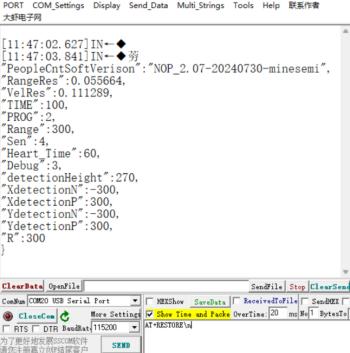
AT+READ\n | Read Firmware Version and Parameters |
AT+DEBUG=X\n | Switch Protocol (default: 3) (1 = String Mode, 2 = Test Mode, 3 = Working Mode) |
AT+TIME=XX\n | Data Output Interval (unit: ms, range: 100–10000, default: 100) |
AT+RANGE=XXX\n | Configure the Radial Distance (unit: cm, range: 100–2000, default: 300) |
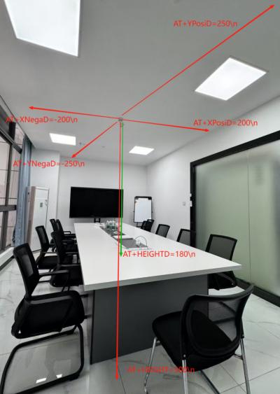
AT+XNegaD=-XXX\n | Configure the X negative boundary (unit: cm, range: 0–300, default: 300) |
AT+XPosiD=XXX\n | Configure the X positive boundary (unit: cm, range: 0–300, default: 300) |
AT+YNegaD=-XXX\n | Configure the Y negative boundary (unit: cm, range: 0–300, default: 300) |
AT+YPosiD=XXX\n | Configure the Y positive boundary (unit: cm, range: 0–300, default: 300) |
Step 1: After sending AT+RESTORE\n, the module restores its default configuration. Previously learned information has already been saved to flash, and the learned data in flash will not be reset
Default Radial Distance: AT+RANGE=300\n 3m
Default Installation Height: AT+HEIGHT=270\n 2.7m
Default Detection Height: AT+HEIGHTD=270\n 2.7m
Default Threshold Value:
AT+XNegaD=-300\n Set X-Negative Boundary
AT+XPosiD=300\n Set X-Positive Boundary
AT+YNegaD=-300\n Set Y-Negative Boundary
AT+YPosiD=300\n Set Y-Positive Boundary
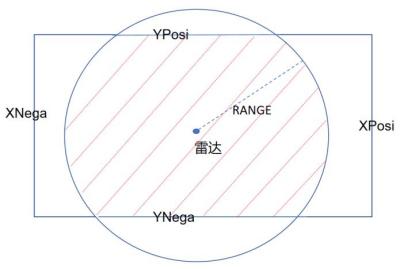
The shaded area indicates the valid region
During normal operation, range parameters should be set according to the actual indoor space. The principle is to avoid scanning large objects such as walls or tables, which may interfere with the module. When configuring via the serial tool, HEX mode can be exited first.
Step 2: Send the range setting commands in sequence and outline the room area.
A successful configuration will return AT+OK=XXX, while a failed configuration returns Save Para Fail. In case of failure, the command should be resent.
Step3: After setting the range parameters, the module is ready for use. Launch the graphical PC software Radar_DemoCeilMountEN.exe.
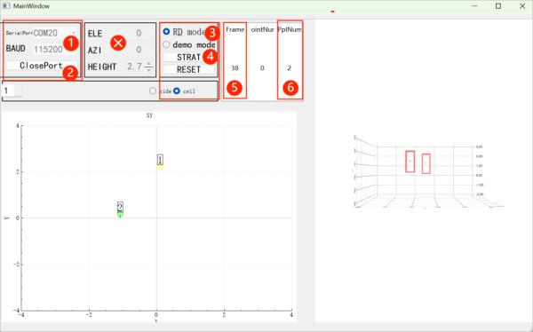
①Select the port number and set the baud rate to 115200
②Open the serial port
③Select Mode
④Click Start
⑤Current Frame Number
⑥Current Number of People
Field | Byte Count | Notes | |
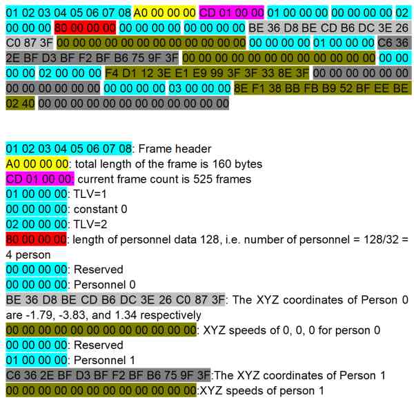
HEAD | 8 | Frame Header: Fixed as \x01\x02\x03\x04\x05\x06\x07\x08 | |
LENGTH | 4 | Total Frame Data Length (uint32) | |
FRAME | 4 | Frame Number (uint32) | |
TLVs | 4 | TLVs = 1, followed by point cloud information (uint32) | |
POINTLENTH | 4 | Point Cloud Length: always 0 (uint32) | |
TLVs | 4 | TLVs = 2, followed by people information (uint32) | |
TRACKLENTH | 4 | People Information Length (uint32) (Number of people = TRACKLENGTH / 32) | |
Person 1 | Q | 4 | Reserved Field (uint32) |
ID | 4 | Person ID (uint32) | |
X | 4 | Person's X/Y/Z coordinates and velocity (float). Coordinates in meters (m), velocity in m/s, precise to two decimal places. Unpack as little-endian single-precision floats per IEEE 754 standard. https://www.binaryconvert.com/convert_float.html https://www.cnblogs.com/guanshan/articles/guan022.html | |
Y | 4 | ||
Z | 4 | ||
Vx | 4 | ||
Vy | 4 | ||
Vz | 4 | ||
…… | |||
Person n | Q | 4 | Reserved Field (uint32) |
ID | 4 | Person ID (uint32) | |
X | 4 | Person's X/Y/Z coordinates and velocity (float). Coordinates in meters (m), velocity in m/s, precise to two decimal places. Unpack as little-endian single-precision floats per IEEE 754 standard. https://www.binaryconvert.com/convert_float.html https://www.cnblogs.com/guanshan/articles/guan022.html | |
Y | 4 | ||
Z | 4 | ||
Vx | 4 | ||
Vy | 4 | ||
Vz | 4 | ||
Step 1: Connect the module to a PC via a UART-to-USB adapter. The wiring is shown in the table below.
MS72SF1 Pin | UART to USB Pin | |
3.3V | → | 3.3V |
GND | → | GND |
RX | → | TX |
TX | → | RX |
Configure the serial communication tool by selecting the corresponding port detected by the computer, and set up the link as follows:
lBaud rate: 115200
lData bits: 8
lStop bits: 1
lParity: None
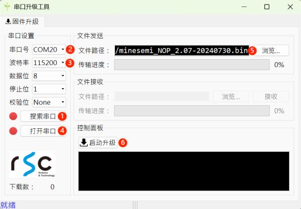
①Search for Serial Ports
②Select Port
③Set the baud rate to 115200
④Open the por
⑤Select the firmware to be flashed
⑥Start Upgrade
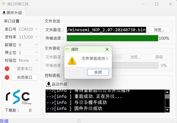
Wait for the progress bar to complete. Once finished, the firmware update is complete. Successful flashing is shown as follows.
Watch the full tutorial video: https://youtu.be/plFVAd2RtYg
Q1: Module unresponsive after power-on?
A: Insufficient supply current. Use a stable 3.3 V, ≥1 A power source.
Q2:In a “people present” environment, the radar may occasionally fail to detect a person, or in a “no people” environment, it may falsely report a person. What could be the possible causes?
A:
Condiction 1: The radar scans a large area, detecting reflections from walls, doorways, or movement on the other side of wooden partition walls.
Adjustment: First complete the learning mode, then set the range according to the scene.
Condiction 2: The radar is positioned directly above running air conditioners or fans.
Adjustment: Reposition the radar so it does not face air conditioners or fans directly.
Condiction 3: Objects sway due to airflow from air conditioners.
Adjustment: Cotton or non-metallic items will not cause false detections. Metallic objects should be secured.
Condiction 4: The radar is not secured, and vibrations cause false detections.
Adjustment: Ensure the radar mount is stable and avoid any shaking or vibrations.
Condiction 5: Occasional movement of pets, birds, or other small moving objects.
Adjustment: The radar is highly sensitive to micro-movements, so this type of interference cannot be eliminated.
Condiction 6: Power interference occasionally causes false detections.
Adjustment: Ensure a stable power supply and minimize voltage ripple.
Q3: Why does the module require learning and calibration?
A: Study stores data of the new environment into flash memory as a reference baseline for operation, helping the module better determine the validity of detected targets. Calibration only needs to be performed during the first use; as long as the position remains unchanged, recalibration is not required. Data after calibration will not be erased by the AT+RESTORE\n command.
Q4: What do TLV, Q, and V mean?
lTLV – TLV serves as a separator between different types of data. 01 00 00 00 is followed by point cloud data, while 02 00 00 00 is followed by people count data.
lQ – A reserved bit (Reserved Bits, abbreviated as RSV) and is always 0.
lV – Velocity
The MS72SF1 millimeter-wave radar sensor module provides a powerful solution for people detection and smart environments. With proper setup, calibration, and parameter tuning, developers can quickly deploy it in applications such as occupancy sensing, smart lighting, security, and building automation.