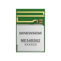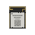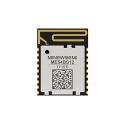


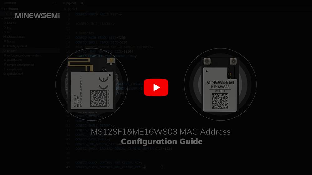
In the growing world of the Internet of Things (IoT), developers often work with modules that support both Wi-Fi and Bluetooth Low Energy (LE) for versatile wireless connectivity. MinewSemi’s MS12SF1 and ME16WS03 modules combine Nordic’s nRF5340 SoC and nRF7002 Wi-Fi 6 companion IC, offering a robust solution for dual-protocol IoT devices.
One important step in deploying these modules is manually configuring the MAC address for the Wi-Fi interface, since the nRF7002 does not come with a factory-programmed MAC address. This blog post walks you through why this matters, and how to properly configure the MAC address for your nRF7002-based module.
The MAC address (Media Access Control address) is a unique identifier for a device on a network. Without a proper MAC address, your device may not connect to Wi-Fi networks or function correctly in an IoT environment.
Nordic's nRF7002 module, while powerful and feature-rich, does not ship with a pre-set MAC address. As a developer, you must manually write the MAC address into the chip's OTP (One-Time Programmable) memory to ensure network functionality and address uniqueness.
These two modules feature the following architecture:
nRF5340 is a multi-protocol system on chip (SoC) and acts as the host processor with the following functions:
1. Acts as the host for nRF7002
2. Runs the user application and the nRF7002 driver
3. Communicates with the nRF7002 via QSPI or SPI
4. Supports multiple wireless protocols including Bluetooth Low Energy, Bluetooth mesh, NFC, Thread, Zigbee, and ANT
5. Features a dual-core architecture with:
128 MHz Arm Cortex-M33 CPU with 1 MB Flash + 512 KB RAM
64 MHz Arm Cortex-M33 CPU with 256 KB Flash + 64 KB RAM
nRF7002 Wi-Fi 6 Companion IC Responsible for:
1. Implements the Physical (PHY) and Medium Access Controller (MAC) layers of the Wi-Fi stack
2. Provides dual-band 2.4 GHz and 5 GHz Wi-Fi 6 connectivity
3. Supports IEEE 802.11ax (Wi-Fi 6) and earlier standards (IEEE 802.11a/b/g/n/ac)
4. Communicates with the host (nRF5340) through SPI or QSPI interface
5. Offers seamless coexistence with other protocols like Bluetooth LE
6.Enables Wi-Fi 6 features such as OFDMA, Beamforming, and Target Wake Time
Together, these components allow simultaneous support for Bluetooth LE and Wi-Fi — perfect for modern IoT gateways, sensors, and edge devices.
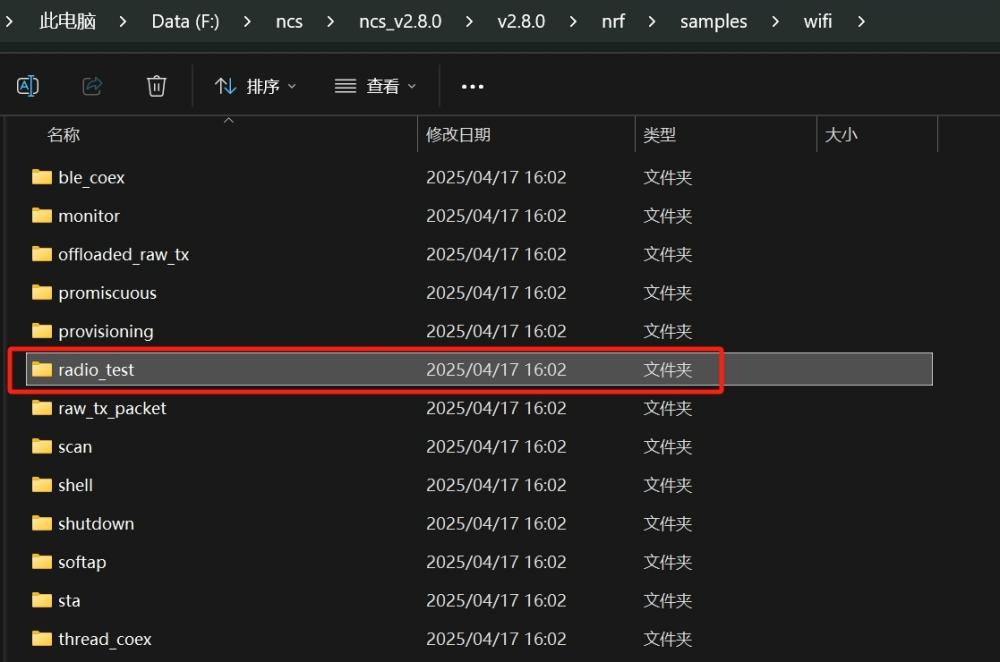
1. Flash the WiFi radio_test example code in NCS (..\nrf\samples\wifi\radio_test) into the nRF5340,
2. Then write the Wi-Fi MAC address into the nRF5340 OTP using the command (wifi_radio_ficr_prog otp_write_params).
Note: OTP is a one-time programmable memory, which means that the value can only be written once. This must be understood before execution.
Operating Steps:
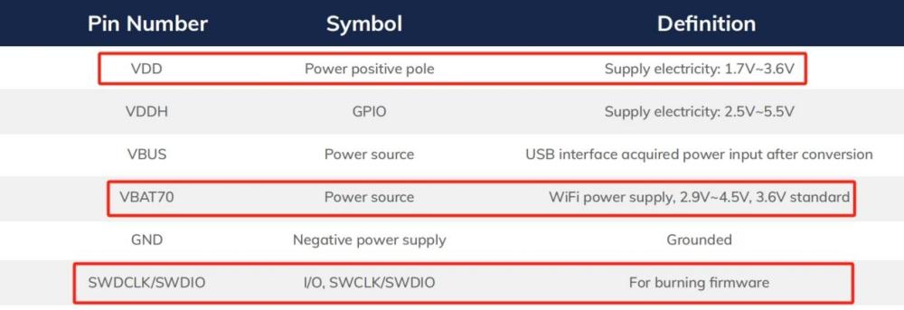
Hardware Connections:
lJ-Link: Connect to appropriate module pins
lOperating Voltage:
lVCC: 2.7V–3.6V (recommended: 3.0V–3.6V)
lWiFi Vbat70: 2.9V–4.5V (recommended: 3.3V–4.5V)
UART Interface:
lTX: P0.06
lRX: P0.05
lBaud Rate: 115200
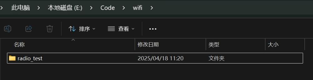
1. Copy the WiFi radio_test example code in NCS (..\nrf\samples\wifi\radio_test) to a commonly used folder. Avoid non-English characters in the path.
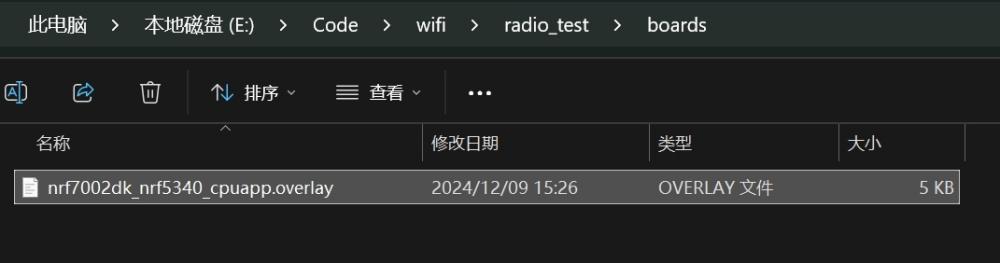
2. Nordic’s example is designed for the nRF7002 DK board, whose internal pin connections differ from MS12SF1 and ME16WS03.
Insert the provided nrf7002dk_nrf5340_cpuapp.overlay file into the (..\radio_test\boards) directory.
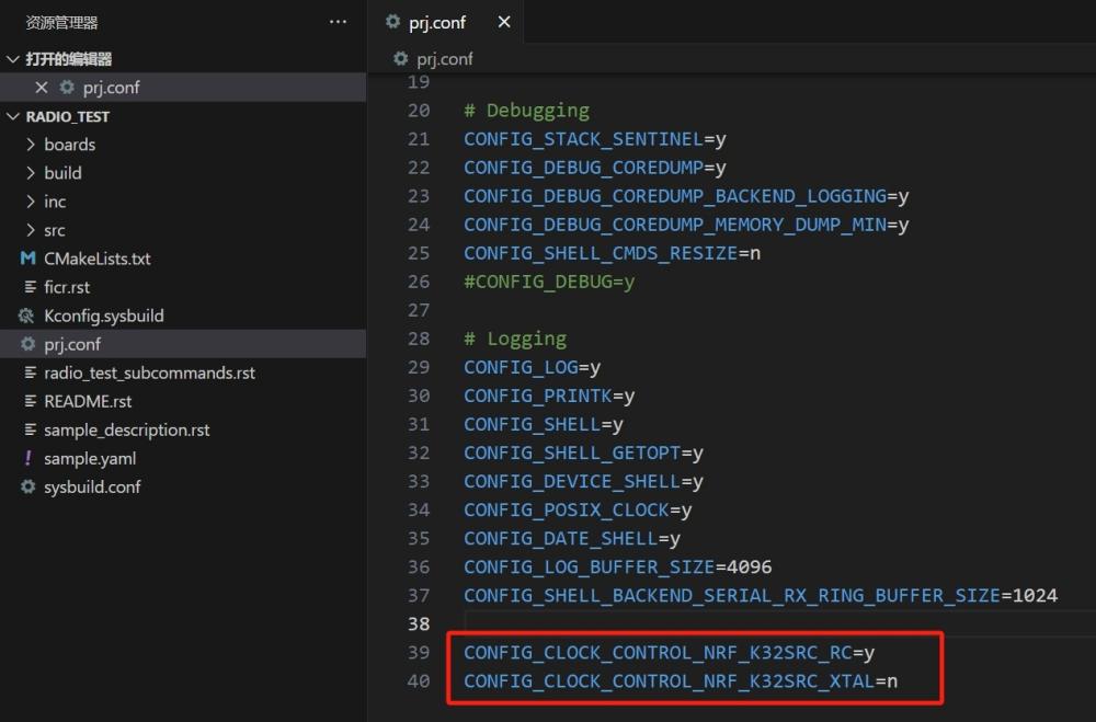
3. In VS Code, open the radio_test project. Since MS12SF1 and ME16WS03 lack an external 32kHz crystal on XL1/XL2 (unlike the nRF7002 DK), disable the default crystal oscillator in the MCU config.
Add the following to prj.config:
CONFIG_CLOCK_CONTROL_NRF_K32SRC_RC=y
CONFIG_CLOCK_CONTROL_NRF_K32SRC_XTAL=n
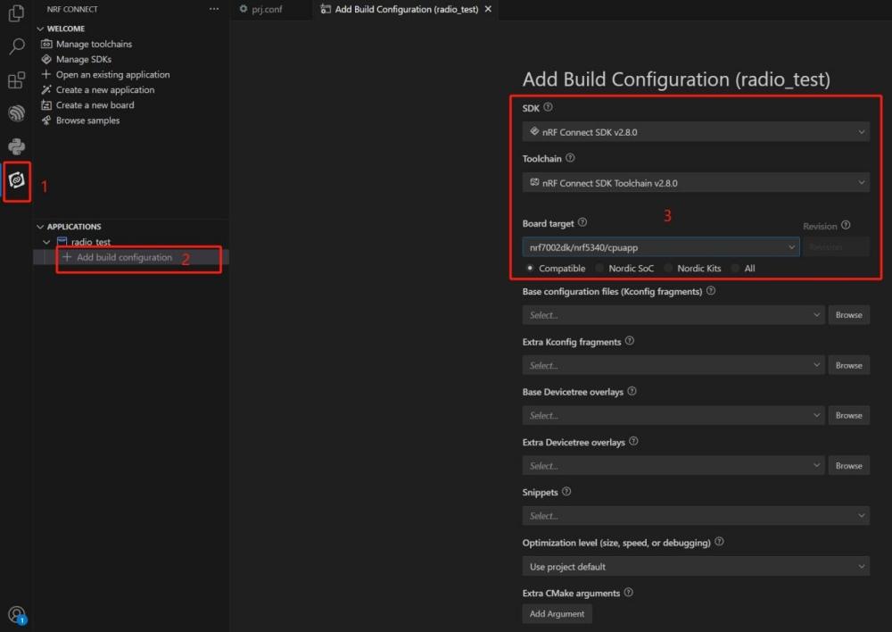
4. Open the nRF Connect extension, add a build configuration:
lSelect the correct SDK and Toolchain
lBoard target: nrf7002dk/nrf5340/cpuapp
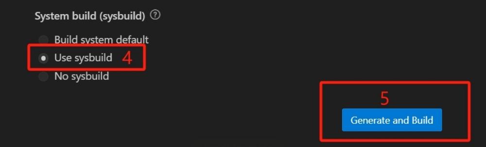
lSystem build: Use sysbuild
lClick Generate and Build
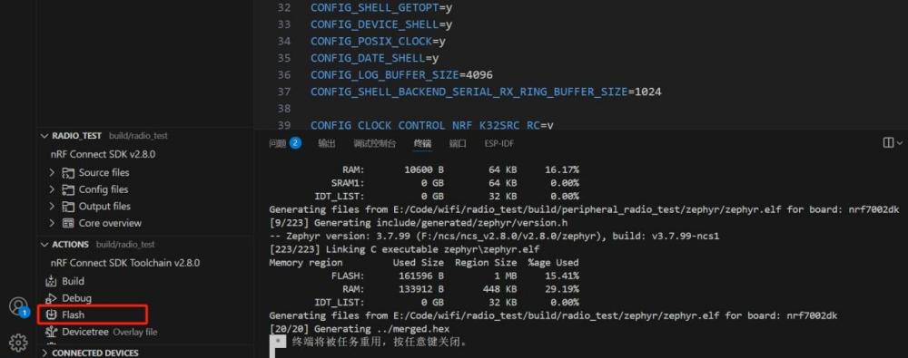
5. After the build, click the Flash button to program the firmware into the module.
Writing and Verifying the MAC Address
1. Connect to the UART of MS12SF1/ME16WS03:
lTX: P0.06
lRX: P0.05
lBaud Rate: 115200
2. Open a serial terminal and enter the following to read the OTP:
wifi_radio_ficr_prog otp_read_params
(Include carriage return and newline)
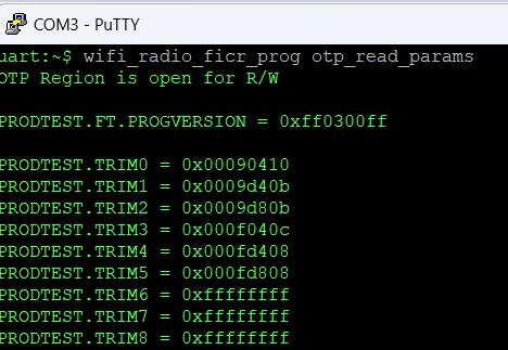
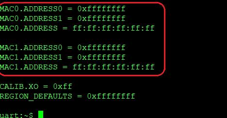
If both MAC0 and MAC1 display a value of 0xFF, as shown above, this indicates that the Wi-Fi MAC address has not been written into the nRF7002's OTP memory.
3. Manually issue the OTP write command to program the Wi-Fi MAC address into OTP. (source: Nordic documentation):
Commands:
1. Write MAC0 (used in STA mode):
wifi_radio_ficr_prog otp_write_params 0x120 0x048C99A8 0x1004
2. Write MAC1 (used in AP mode):
wifi_radio_ficr_prog otp_write_params 0x128 0x048C99A8 0x0004
3. Use the read command again to confirm:
wifi_radio_ficr_prog otp_read_params
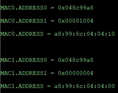
MAC0 and MAC1 should now show the written values.
⚠️ Warning: OTP memory can only be programmed once (1 → 0). You cannot overwrite a written address.
By following this guide, you can ensure your nRF7002-based Wi-Fi 6 modules are correctly configured for reliable network performance. This step is crucial for any project involving dual-protocol IoT connectivity, especially in smart home, industrial, or wearable applications.
For more tutorials and updates on MinewSemi's wireless connectivity modules, stay tuned to our blog or visit minewsemi.com.